V9958 YJK (YUV) mode
Some time ago we introduced a tiny tool called ppmview.prg in our collection of tools and progs for our Steckschwein. The ppmview.prg, as the name already tells, is able to load an image in ppm (Portable BitMap) format with a maximum size of 256x212px and displays it on the screen.
The first version of ppmview was released in 2018 and since then we just use the SCREEN 8 (MSX) also known as graphic mode 7 (RGB).
Mode 7 is a bitmap mode where we have 256 colors available and each pixel requires 1 Byte for their color information.
The 1 Byte color information must be stored in VRAM encoded as GRB 3:3:2 (green, red, blue), which means 3 Bit green, 3 Bit red and 2 Bit blue.
On the other side we have the PPM color information - which is 24Bit RGB - so we have to adapt or map the 24Bit to our 8 Bit GRB color value in some way.
It becomes apparent that this comes with a price, namely the loss of color information. Especially the blue part of the pixel is just 2 Bit, hence we have 4 levels of blue per pixel available only.
The following screenshot from our Emulator shows the loss of color information.
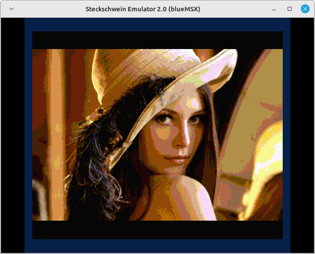
There must be more to it…
In the technical documentation of the V9958 one can read that there where some registers added. Beside the horizontal scroll registers R#26, R#27, register R#25 was added and offers 2 interesting Bits we’ll now focus on. These are Bit 4 and Bit 3 in R#25.
YJK-Type Data Display Function R#25
| Bit 7 | Bit 6 | Bit 5 | Bit 4 | Bit 3 | Bit 2 | Bit 1 | Bit 0 |
|---|---|---|---|---|---|---|---|
| YAE | YJK |
If Bit 3 of R#25 is set the V9958 will read the data from VRAM and interprets them as YJK typed data. The VDP converts the YJK data to corresponding RGB signals via the internal DAC which has 5 Bit per color part (RGB). All we have to do now is just encode the 24Bit RGB value given in the ppm file to appropriate YJK values in the VDP RAM. From the datasheet we can find out that 4 Bytes in VRAM are grouped together to encode the YJK data for 4 consecutive pixels.
YJK Data in VRAM for 4 pixels
          | C7 | C6 | C5 | C4 | C3 | C2 | C1 | C0 |
          |----+----+----+----+----+----+----+----|
1st pixel |           Y0           |      KL      |
2nd pixel |           Y1           |      KH      |
3rd pixel |           Y2           |      JL      |
4th pixel |           Y3           |      JH      |
Furthermore the forumlas to convert the RGB data to YJK representation is given in the datasheet with
from RGB to YJK
Y = B/2 + R/4 + G/8
J = R – Y
K = G – Y
The Y value specifies the brightness and may vary for each pixel, but the color information (chrominance), given as J and K, is shared among 4 pixels. Somehow we have to derrive or calculate the J and K values upon the RGB information of 4 adjacent pixels in the ppm file. There are various approaches available for doing that, i decided to use a lightweight kind of chroma- or color- sub-sampling based on the 4:1:1 approach.
Lightweight 4:1:1 color sub-sampling
The idea behind color sub-sampling is to use the average of each component (RGB) from 4 pixels and calculate a median Y upon the formula given above. But we need to be careful to round the result during the calculation.
R_a = round((R0 + R1 + R2 + R3) / 4)
In 6502 assembly there is no DIV instruction nor can we round up the result of a calculation. But we can easily shift left and right. We end up in some code like this
    CLC
    LDA #2                    ; R_a = ((R0 + R1 + R2 + R3 + 2)>>2); B_a, G_a same manner
    ADC yjk_chunk+yjk::R0,Y
    ADC yjk_chunk+yjk::R1,Y
    ADC yjk_chunk+yjk::R2,Y
    ADC yjk_chunk+yjk::R3,Y
    LSR
    LSR
    STA yjk_chunk+yjk::R_a,Y
    ...
R0..R3 are the R component of the 4 adjacent pixels which we read from the ppm file beforehand. In R0..R3, G0..G3 and B0..B3 we store the 5 higher Bits of the RGB value from the ppm file only. This is because the Y0..Y3 values are also just 5 Bits wide. Just to mention it, for the entire calculation we only require the 8 Bit range. This fits perfectly to our CPU, we never overflow (carry) and thus can avoid using expensive 16Bit values.
As can be seen in the code, we also add #2 to the sum of the R0..R3 components. This is for “rounding up”, cause if we divide by 4, which is simply 2 shifts right (LSR) on 6502, we’ll otherwise lose the fraction. To avoid this we round up by using the fact that
  round(A/B) = (A + (B/2)) / B

  e.g. round(5/2) = 1.5 = 3 with our equation
       (5 + 2/2) / 2 = 3 FTW!
With the average RGB values R_a, G_a, B_a we can calculate the average of Y with the formula given from the datasheet.
Y_a = round(B_a/2 + R_a/4 + G_a/8)
Some transformation to ease the 6502 coding, we end up in
  Y_a = (4*B_a + 2*R_a + G_a + 4) / 8 # rounding is replaced with +4
      = ((B_a << 2) + (R_a << 1) + G_a + 4) >> 8
and in 6502 assembly
    ASL yjk_chunk+yjk::B_a  ; B_a << 2
    ASL yjk_chunk+yjk::B_a
    LDA yjk_chunk+yjk::R_a  ; R_a << 1
    ASL
    CLC
    ADC yjk_chunk+yjk::B_a
    ADC yjk_chunk+yjk::G_a
    ADC #4                  ; +4 for round up
    LSR                     ; DIV 8
    LSR
    LSR
    STA yjk_chunk+yjk::Y_a
The J and K values can now be calculated upon the formulars from the datasheet, and are just the difference between Y_a and R_a and G_a, respectively.
    J = R_a - Y_a
    K = G_a - Y_a
and in 6502 assembly it’s just a simple subtraction.
    SEC                       ; J = R_a - Y_a;
    LDA yjk_chunk+yjk::R_a
    SBC yjk_chunk+yjk::Y_a
    STA yjk_chunk+yjk::J
    ...
Now that we have J, K available we can calculate back the Y0..Y3 values for each pixel. Again we have to use the formular Y = B/2 + R/4 + G/8 from the datasheet and apply them for each pixel. We use the same transformation from above to get simple 6502 assembly code.
    LDA yjk_chunk+yjk::B3,Y   ; Y3..Y0 = round(B0/2 + R0/4 + G0/8) = (B0<<2 + R0<<1 + G + 4) >> 3
    ASL
    ASL
    STA yjk_chunk+yjk::B3,Y
    LDA yjk_chunk+yjk::R3,Y
    ASL
    CLC
    ADC yjk_chunk+yjk::B3,Y
    ADC yjk_chunk+yjk::G3,Y
    ADC #4
    AND #$F8                  ; !!! we do not >>3 (div 8) but mask out bit 2..0 since the y value
    STA yjk_chunk+yjk::Y3,Y   ; in vram has to be placed as bit 7..3 and bit 2..0 are the k/j component
The calculation from Y3 down to Y0 can be done in a loop, that’s why i use the indrect addressing mode. There is an appropriate yjk struct (ca65 assembly) which is structured in a way that we easily can count down the index.
Note that the DIV 8 step is intentionally left out here, but rather we mask the result with #$F8. That’s because the Y values in VRAM must be stored in Bit 7..3 which is exactly our result so we must not shift to right 3 times just to shift left 3 times while combining with J, K ;)
The rest of the code is easy, we just combine the calculated Y0..Y3 values with J,K.
    LDA yjk_chunk+yjk::K      ; Y0 with K low
    AND #$07
    ORA yjk_chunk+yjk::Y0
    STA a_vram
    LDA yjk_chunk+yjk::K      ; Y1 with K high
    LSR
    LSR
    LSR
    AND #$07
    ORA yjk_chunk+yjk::Y1
    STA a_vram
    ...
for Y2,Y3 in the same manner but with J.
Finally we putting it all together and enhance our ppmview.prg with the YJK mode, also known as SCREEN 12 in MSX Basic. We also add an option -rgb to support the “old” RGB mode still.
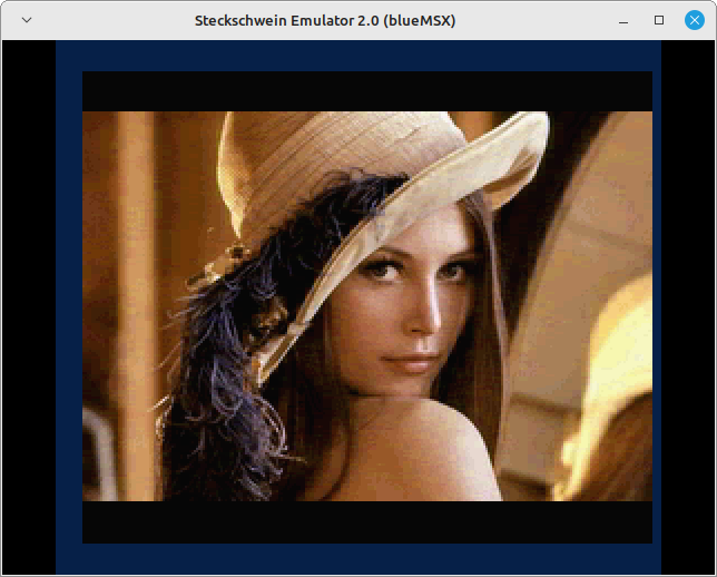
I think the result in YJK mode, especially when used with fotos, is very impressive and even though we have followed the simple approach of sub-sampling only.
The source of ppmview and the ppm library are available at Github.
What we did not focussed on yet is the YAE (Bit 4) in R#25. The so called SCREEN 10 and SCREEN 11 modes (MSX Basic). Maybe this is something we will have a look in the future.
Further readings and investigations whether this mode was being used in MSX2/MSX2+ at all, i found interesting articles about the YJK mode (see links below). As far as i can see there is no game or kind of which is using this mode “heavily” (yet) ;)